Using GNS3 to learn SDN
Setup and configure your GNS3 with required elements to learn, develop and test Software Defined Networks.

I am a MS CS graduate student at Georgia Tech. I am building my skills in security and software engineering.
GNS3 is a network simulation platform for creating and testing virtual networks with routers, switches, and other devices. There are many other alternatives to GNS3, but I prefer GNS3 since the UI is user-friendly, supports multiple types of network devices and protocols and more importantly has integrations with Docker, VirtualBox and VMware.
In one of my previous blog articles, I presented a brief and elementary introduction to Software Defined Networks. In this blog article, we shall walk through setting up GNS3, and further implement a simple controller using RYU framework on a network of SDN switches in GNS3.
Setup
Installing GNS3
Follow the instructions provided in the GNS3 documentation to install GNS3 in your computer system. The following link references a document that walks through the installation of the GNS3 server and client in a Linux machine: https://docs.gns3.com/docs/getting-started/installation/linux. The navigation bar on the left has installation instructions for other OSes.
Downloading Open vSwitch
Once GNS3 is installed on your computer system, let us import the Open vSwitch appliance into GNS3.
Note: The following instructions are based on GNS3 macOS client version 2.2.37
On the left vertical navigation bar, select one of the icons to open a drawer showcasing a list of available devices. On the bottom of this drawer, click on the button that says "New template".
A new window with the title "New template" opens. Select the "Install an appliance from the GNS3 server (recommended)" option (It is selected by default) and click "Next >" on the bottom corner of the window.
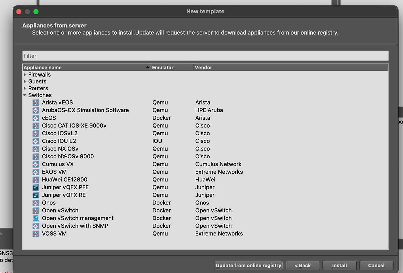
Click on “Update from online registry” to fill the appliances list.
Once the appliance list is filled, find and click “Open vSwitch” under the “Switches” accordion as illustrated in Figure below. Then click on “Install” found in the bottom corner of the window.
For simplicity, use the default settings for the rest of the installation process.
Setting up RYU
RYU is going to be set up on your host machine (or, in the gns3 server if you are using one). This section shows how to set RYU in a Linux or *nix-based machine.
Assuming that you have
python3,pip3, andvirtualenvinstalled in your host machine, create a virtual environment by running the following command:virtualenv venvActivate the created virtual environment by running:
source ./venv/bin/activateInstall
ryufor this environment by running:pip install ryu
NOTE: Before moving forward ensure that ryu is correctly installed and is working by running
ryu-managerin a terminal withvenvactive.
Simple Experiment
In this experiment, a network containing a single Open vSwitch will be used. The Open vSwitch will be connected to the controller (host machine) through a NAT at eth0. Two host computers will connect to the switch at eth1 and eth2. The goal is to enable communication between the two hosts through the switch.
Configure Open vSwitch
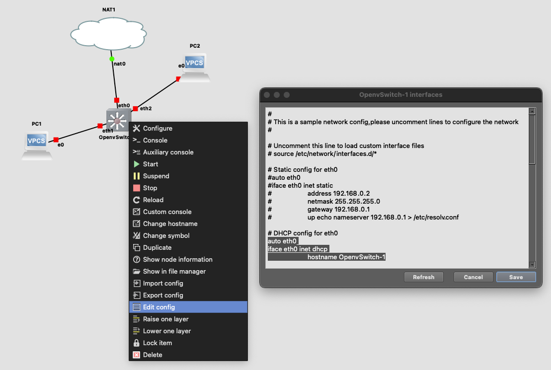
Figure below illustrates the network topology used for this experiment. Before starting up the Open vSwitch node, right-click on the node to “edit config”. Uncomment the section under # DHCP config for eth0. By this configuration, the switch’s eth0 interface will obtain an IP address and other details from the DHCP server which is NAT1 in this case.
Recall: Other details?
Then, start the Open vSwitch node and spawn an Auxiliary console. In the console, enter the following command to instruct the switch to use the specified controller for the specified bridge.
# Set controller IP
ovs-vsctl set-controller br0 tcp:192.168.122.1:6633
Ensure that the IP address used in the above command is in fact the IP address of one of the interfaces on your host machine where the GNS3 server is installed.
Configure the PCs
Similar to the switch, right-click on each PC and edit their configuration. Set manual IP address by inserting the following configuration in PC1 and PC2 respectively:
# For PC1
ip 10.0.0.10/24 10.0.0.1
# For PC2
ip 10.0.0.11/24 10.0.0.1
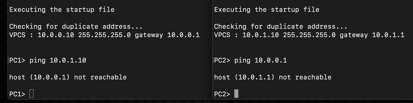
Verify that the two PCs are not able to ping each other.
Configure the controller
Let us begin by writing the controller framework. In your host machine, create a file by the name controller.py and fill in with the following code:
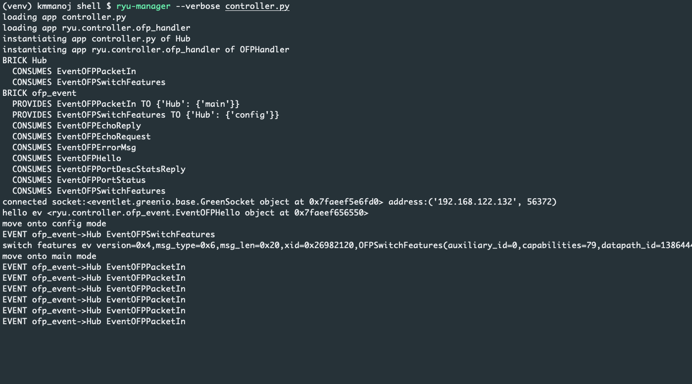
Then, to start the controller process run the following command in the host machine in the terminal where venv is active: ryu-manager --verbose controller.py . The logs in the terminal should indicate that the switch registered itself with the controller and is receiving PacketIn events from the switch.
Explanation
RYU is built on an event-based framework. The above code responds to two events: SwitchFeatures and PacketIn events. The SwitchFeatures event is triggered by the switch when it registers itself with the controller. The PacketIn event is triggered by the switch when it sees a packet that does not match any flow rule but the fallback rule. The fallback rule is set during the registration phase of the switch (as implemented in line 12–31). While, for each packet flowing in the data plane the packet_in_handler function is called. The controller instructs the switch to broadcast the packet (line 40) to all the ports other than the port in which the packet was received i.e. in_port .
Verification
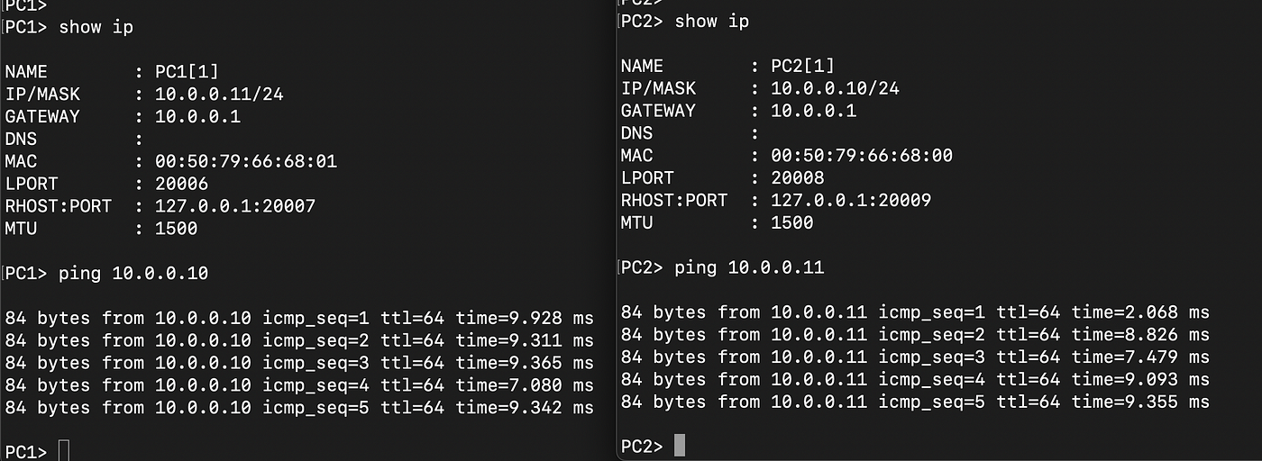
Now, ping PC2 from PC1 and vice-versa. Observe that the two hosts are able to communicate with each other, as shown in Figure below (Unlike shown in the previous Figure where they weren't reachable).
Further, in the GNS3 UI right-click on the link connecting the NAT and the Open vSwitch, and select capture packets. Then, run ping from one of the PCs to the other PC. Observe that there are OpenFlow packets surrounding the ICMP request and reply packets that make communication between PCs possible.
Think: Why does the link connecting NAT and Open vSwitch see ICMP packets between the two PCs?

Conclusion
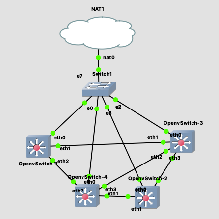
The above blog article demonstrates the usage of GNS3 to set up, build and simulate SDN networks. To build a multi-switch topology one could use a standard ethernet switch to connect the NAT to all the Open vSwitches, as shown in Figure below.
The controller code used here performs no more than the job of a network hub. I would strongly suggest you learn how to develop a controller that performs L2 switching. Further, learn how to develop a controller that performs L3 switching. What about a controller that manages a cluster of switches performing L2 and L3 switching?
I hope this blog article helped you clear up your obliviousness for SDN and enabled you to take the first step towards learning SDN. Learn by doing!


